Safety Notice: These instructions are intended to provide guidance for safe and proper operation of a Metal Samples Packing Gland and retractable device (probe, coupon holder, injection system, etc.) Failure to adhere to this procedure could result in physical injury to personnel and/or damage to plant equipment. Do not attempt to operate a Metal Samples Packing Gland and associated hardware unless you have read and understood these instructions. If you have any questions, please contact our offices prior to attempting to use these products.
System Overview
The Metal Samples Packing Gland is designed to achieve and maintain a seal on the insertion rod of a retractable device such as a corrosion probe, coupon holder, or injection system, while still allowing it to move freely. This allows the device to be installed and removed from a system while it is under pressure. (NOTE: This requires the use of an isolation valve which is sold separately.)
It is important to familiarize yourself with the components of the Packing Gland and retractable system before attempting to use it. The diagram to the right illustrates the components of the Metal Samples Packing Gland assembly. |
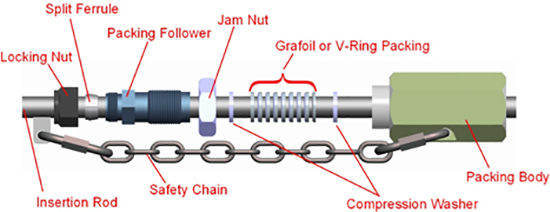 |
|
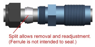
It is also important to note that the Ferrule is not responsible for achieving a seal. It serves as a mechanical stop (discussed later) and is split to prevent it from locking permanently onto the rod. If a leak occurs, tightening the Locking Nut and Ferrule will not stop it. |
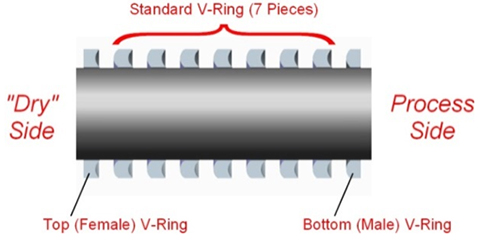
Packing is available in two materials: Teflon® and Grafoil®. Table 1 lists key points of each material.
| Table 1. Packing Materials |
| Material |
Service
Temperature |
Special Notes |
| PTE (Teflon®) Packing* |
500° F (260° C) |
Excellent Chemical Resistance.
Can be used repeatedly.
Must be oriented properly (see diagram). |
| Grafoil® Packing |
850° F (454° C) |
High Temperature Service.
One-time use (typical).
Orientation does not matter. |
|
 |
The basic tools1 required to adjust and mount a Metal Samples Packing Gland are listed in Table 3. |
| Table 3. Tools and Supplies |
Quantity |
Tool or Supply |
|
Quantity |
Tool or Supply |
| 2 |
1” Open-End Wrench2 |
1 |
Pipe Wrench |
| 1 |
1.5” Open-End Wrench2 |
N/A |
Pipe Sealant (tape or paste) |
| 1 |
1.75” Open-End Wrench2 |
N/A |
Anti-Seize Compound |
|
Adjustment Procedure
In either case, it is imperative to ensure that you have the correct number of packing rings installed to achieve the proper compression. Table 2 lists the number of packing rings for each type of packing, and for each rod size. |
| Table 2. Packing Ring Quantity |
| Rod Size |
3/8” Diameter |
1/2" Diameter |
5/8" Diameter |
| PTE (Teflon®) Packing* |
5 |
6 |
9 |
| Grafoil® Packing |
6 |
7 |
7 |
|
Notes:
1 Additional tools may be required for associated equipment (such as flange bolts).
2 If the correct sized open-end wrenches are not available, two adjustable wrenches may be used.
The adjustment procedure for a Metal Samples Packing Gland is as follows:
Note: The Packing Gland must be adjusted prior to installation onto the system.
Note: Apply anti-seize compound to threaded components to prevent galling.
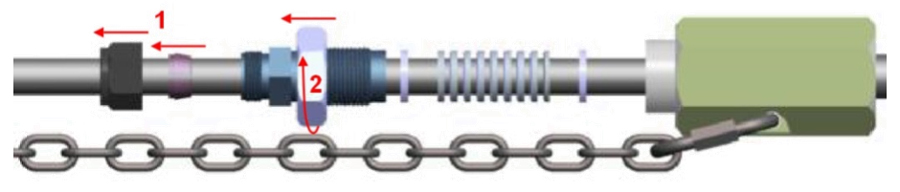
- Loosen the Locking Nut. Slide the Locking Nut and Ferrule away from the Packing Follower.
- Thread the Jam Nut to the top of the Packing Follower.
- Slide the Compression Washers and Packing into the Packing Body.
- Slide the Packing Follower down and begin to thread it into the Packing Body. After a few turns, you should start to feel resistance as the Packing begins to compress.
- Using the hexagonal wrench flats on the top of the Packing Follower, tighten the Packing Follower to the torque specified in the table below.
Caution! MAKE SURE the Jam Nut does not bottom out against the Packing Body at this time. |
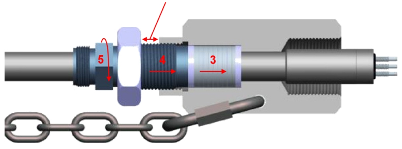 |
Table 4. Recommended Torque Settings
| Pressure Rating |
150 psi |
500 psi |
1,000 psi |
2,000 psi |
| PTE (Teflon®) Packing |
240 in·lb
20 ft·lb |
240 in·lb
20 ft·lb |
300 in·lb
25 ft·lb |
300 in·lb
25 ft·lb |
| Grafoil® Packing |
180 in·lb
15 ft·lb |
180 in·lb
15 ft·lb |
240 in·lb
20 ft·lb |
240 in·lb
20 ft·lb |
Caution! Do not over-tighten the packing. This will result in damage to the packing or the gland.
- After tightening the Packing Follower to the specified torque, the Insertion Rod should be held tightly in the Packing Gland, but you should still be able to push it in and out of the Packing Gland by hand with some effort. NOTE: Some resistance should be felt when sliding the Insertion Rod. It should not slide freely. If the Insertion Rod will slide freely through the Packing Gland, the Packing has not been adjusted properly and a seal will not be achieved.
- Once you have confirmed that the Packing has been properly adjusted, tighten the Jam Nut against the Packing Body. This will lock the Packing Follower in place.
- Retract the Insertion Rod completely. The probe head should bottom-out inside the Packing Body.
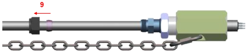
- The Packing Gland is now ready for installation. Do NOT install the Ferrule and Locking Nut at this time. Keep them near the top of the Insertion Rod, clear of the Packing Follower.
Note: The following steps may require a certified pipe fitter for complete installation.
- If using an NPT mounted packing gland, coat the male threads of the mating nipple with an appropriate pipe sealant.
- Mount the Packing Gland on the Nipple or Flange and secure in place. The rod should be fully retracted at this time with the Locking Nut and Ferrule clear of the Packing Follower.
- Open the isolation valve and check the Packing Gland for leaks. NOTE: The Insertion Rod may move when the valve is opened. Stay clear.
- If a packing leak is found, close the isolation valve immediately and attempt to correct the problem using the following procedure:
a.
Loosen the Jam Nut.
b.
Tighten the Packing Follower one-quarter turn.
c. Tighten the Jam Nut and return to step 12.
If the leak cannot be stopped by continued tightening of the Packing Follower, cease installation and contact Metal Samples for support.
- Once the Packing Gland has been confirmed to be leak-free, insert the device to the desired length. See Safety Note 2 below.
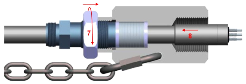
- Hold the Insertion Rod in position and secure it using the Locking Nut and Ferrule. The Locking Nut should be hand-tightened, then wrench-tightened an additional one-quarter to one-half turn.
- Adjust the Safety Chain following the safety chain installation instruction sheet (https://www.alspi.com/chain.htm).
- If a supplementary safety device (such as a Safety Clamp) is being used, mount it at this time.
Safety Notes
- For replaceable rod assemblies, a Safety Nut or Shield must be used.
- At operating pressures greater than 150 psi, Metal Samples requires the use of an Easy Tool Retracting System to ensure safe operation.
- All retractable Packing Gland components and related equipment must be evaluated periodically for leaks, wear, or any unsafe conditions.
Teflon® is a registered trademark of DuPont.
GRAFOIL® is a registered trademark of NeoGraf Solutions
|